It’s a common problem that I’m sure many of you have experienced: You find yourself with a PCB 352C68 accelerometer but no ICP signal conditioner to connect it to your recorder.
No?
Let me start over. Suppose you want to know how something sounds on the inside, by listening to the vibrations transmitted through its structure. Like this:
Be sure to watch the video with its sound. That’s not a microphone; it’s an industrial accelerometer that measures extremely fine vibrations, like a contact microphone.
Unfortunately, industrial accelerometers are designed to be connected to industrial data acquisition systems that cost many thousands of dollars, not to cheap audio recorders, and so I needed an adapter. Why? Partly to listen to watermelons, but more on that later.
A word on recording vibration
Recording vibration is common enough. Many acoustic guitars come with a “piezo pickup” that converts vibrations in the guitar’s body into signals for your amplifier or recorder, so you don’t need to use a microphone that might pick up background noises. You can use the same principle for many acoustic instruments, and professional sound effects designers have used this trick for years. If you want to record an unusual sound without any background noise, why not record the vibrations directly from the source?
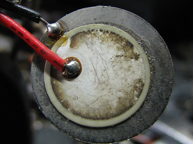
In this application, sound designers and field recordists use what they call “contact microphones”. Contact microphones are made from a piezoelectric crystal sandwiched between pieces of metal:
A piezoelectric disk buzzer, such as you might turn into a DIY contact microphone. Photo by Gophi, CC BY-SA 3.0, via Wikimedia Commons.
A piezoelectric crystal produces a voltage when it is compressed. If you place it on an object that vibrates, the vibrations push on the crystal, and the crystal produces a voltage you can record just like the voltage from a microphone. You can make a DIY contact microphone using a cheap piezoelectric buzzer, or order premade versions, such as from Jez riley French or Cortado. Creative field recordists place their contact microphones on just about anything, discovering strange noises from things as mundane as chain link fences, suspension bridges, dead trees, and ice cracking on a frozen lake.
When a PCB 352C68 meets a watermelon
Vibration recording is also very common in science and industry. Consider some examples:
Your job is to ensure new car engines meet legal noise requirements and don’t rattle, shake, or vibrate in ways that wear out parts or irritate drivers. You need to measure how they vibrate.
You work in a facility full of heavy machinery with motors, gears, and pumps. If a machine unexpectedly fails, the company loses lots of money. You want to measure vibration in the motors and bearings so you can tell if one is wearing out and needs to be replaced.
You’re designing a lightweight structure for a vehicle. You want to know how that structure will flex and vibrate when it hits bumps and potholes.
These scenarios happen every day in engineering and industrial firms, and so specialized tools exist to measure all kinds of vibration. These are generally called “accelerometers.” Unlike the accelerometer in your phone that measures which direction is up, they are designed to measure vibration, often up to tens of thousands of Hertz, and they do so very precisely. Most accelerometers use piezoelectric crystals, just like in contact microphones, but in enclosed metal housings. A good accelerometer comes with a calibration certificate that states exactly how many millivolts of signal it produces for every g of acceleration it experiences, and a chart of how that changes with vibration frequency. A good accelerometer will withstand large vibrations in tough environments filled with heat, oil, and solvents, and will cost you hundreds or thousands of dollars.
Coincidentally, my father falls in category #1 above. For many years, he was a Noise, Vibration, and Harshness (NVH) engineer in the automotive industry. He used accelerometers and measurement microphones routinely in his work, and he still has an uncanny ability to identify engine problems by their sound.
Naturally, when I was a kid – and I’m sure you’re thinking the same thing already – all we wanted him to do was to use his technical abilities to tell us which watermelons are ripe.
Folk wisdom holds that you can knock on watermelons to judge their ripeness. A good watermelon sounds hollow and resonant, not dead or muted. Presumably this has something to do with the stiffness of the flesh, the amount of water it contains, and maybe some chemical changes in its structure as it matures. And if your dad has expensive measurement equipment, why not use it to measure the ideal watermelon?
So that’s what we did. One summer in high school, I was part of the Young Engineers and Scientists program at the Southwest Research Institute, and part of the program asked us to develop our own science project to run over the summer. I chose to study watermelons, and asked Dad for some technical support. He turned to PCB Piezotronics and asked if they might have an accelerometer that could be used for a science project – maybe one that was slightly out of spec or had been returned. To our surprise, we soon received a spotless model 352C68, and off we went.
The experiment was simple. Dad brought home a high-end laboratory data acquisition system and hooked it to his laptop, while Mom selected eight watermelons for test. We strapped the accelerometer to one side of the watermelon and gently tapped the other side with a small wrench. The result was eight recordings with surprising variety. Just listen to how different Melon A is from Melon C:
Melon A:Melon C:
Then Dad invited over some coworkers for a party, and everyone tasted the watermelons and gave them ratings. Using professional acoustics software, we extracted various features from the signals, such as resonant frequencies and reverberation times, and I plugged the numbers into Excel in the hopes of producing a prediction system.
Unfortunately, with only eight melons it’s hard to build a sophisticated model. (Also I was in high school, had never taken a statistics class, and had only a fuzzy understanding of what regression does.) We did note that the mushy and overripe melons were easy to distinguish from the rest, because the mushy ones had no reverb and the knocks damped very quickly. But that’s as far as we got. We considered collecting more data, but eventually I left for college and the accelerometer sat in the closet.1
The basics of ICP signal conditioning
Recently I found the accelerometer again and wanted to try it out. But I hit a snag: Industrial accelerometers are not like microphones or headphones and don’t plug into ordinary recorders or amplifiers you might use for podcasting or music. They use a system variously called ICP, IEPE, DeltaTron, CCLD, or IsoTron by different manufacturers. The short version is this: Signals from piezoelectric crystals have high impedance, so when they are plugged into a typical amplifier or audio recorder, they sound quite tinny. You need to use a specific type of preamplifier that can convert the output to a low-impedance signal. ICP accelerometers have these preamplifiers built in, but to make those electronics work, they require a power source. To provide that power and also transmit the signal, they use a coaxial cable.
The center conductor of the cable carries the power, from a constant-current supply usually set at 4 mA and 18-30 V. The shield acts as ground. The accelerometer’s integrated electronics consume the 4 mA supply, and the voltage across the accelerometer varies in proportion to the amount of acceleration it experiences – record the voltage and you have the signal. In the case of the PCB 352C68, measurements of ±50 gs of acceleration become ±5 volts. So whatever device you plug the accelerometer into must have the ability to supply the right power and then extract out the signal.
(Professional condenser microphones also have integrated electronics, and receive 48 volt “phantom power” over the same cable that conducts the microphone signal. But the details are different, and you can’t just hook an ICP accelerometer to phantom power.2)
Because industrial accelerometers output a precisely calibrated voltage signal, they are typically plugged into precisely calibrated measurement equipment. Much of this equipment can provide the necessary power. If not, you can always buy a “signal conditioner”: plug it between your accelerometer and your recording device and everything will work great.
Signal conditioners are designed to be plugged into specialized test equipment, not commodity recording equipment. They come with BNC connectors for coaxial cables to be plugged into industrial data acquisition hardware, not with standard audio connectors (like phone jacks or XLR cables).
I’m just a guy who wants to record funny noises. I don’t care about calibration, and I don’t want to pay hundreds of dollars for a signal conditioner and thousands more for a special data acquisition system.
Back in high school I built a simple signal conditioner, in anticipation of further watermelon experiments. It was based on a circuit design from an expert in the field, shoehorned into a small plastic box from Radio Shack. It required three nine-volt batteries so it could provide 27 volts, but that made it bulky; instead of a constant-current supply, it used a resistor to limit the total current; and the only output was a 3.5mm audio jack. I wanted to create a new version using a better circuit design, a shielded metal enclosure, and more convenient output jacks for connection to recording equipment.
Fortunately the pandemic has supplied limitless boredom. So how can we make this problem more complicated while solving it?
Electronics for a DIY ICP supply
The first problem was understanding the circuit I needed to build so I could buy the right parts. Unfortunately, it turns out that very few people have made their own ICP power supplies, or if they have, they haven’t posted it on the Internet. (I’m sure many technicians and engineers have built or repaired them in the course of their work.) The only detailed example I found was Project 134 from Rod Elliott of Elliott Sound Products, who follows the “Why buy a part when I can build it myself?” design philosophy. His version requires wall power, a transformer, and electronics to produce a 24 V DC supply, but I wanted something battery powered and simpler.
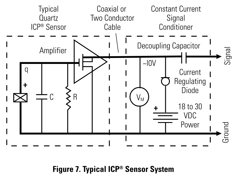
After stumbling around, I discovered a PCB manual that provides a handy diagram of their ideal circuit:
The signal conditioner consists of a well-regulated 18 to 30 VDC source (battery or line-powered), a current-regulating diode (or equivalent constant current circuit), and a capacitor for decoupling (removing the bias voltage) the signal…. The current-regulating diode is used instead of a resistor for several reasons. The very high dynamic resistance of the diode yields a source follower gain which is extremely close to unity and independent of input voltage. Also, the diode can be changed to supply higher currents for driving long cable lengths. Constant current diodes, as shown in Figure 8, are used in all of PCB’s battery powered signal conditioners.
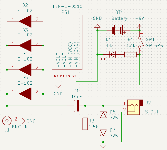
Current-regulating diodes turn about six different components from Project 134 into a four parts you can order for 97 cents each from Mouser. (Four because each current-regulating diode supplies 1 mA.) My previous rat’s nest of electronics was the resistor-based design PCB warns against, so I started sketching out a new design:
The Accelerominator 3000 ICP power supply.
Some notes on the components used:
The power passes through a Traco TRN 1-0515, a regulated DC-DC converter that boosts 9 volts to 24 volts. It’s a switch-mode power supply rated for a minimum 100 kHz switching frequency and 45 milliamps of output. It’s nice because it’s tiny and it’s rated for a suitably low power; I tried using a Pololu adjustable supply that was rated for multiple amps, but I was drawing so little power that the switching supply would skip pulses periodically. Unfortunately the frequency at which it skipped pulses was in the audible range, so this manifested as high-frequency noise in the audio signal.
R3 is not strictly necessary, but allows smartphones to recognize input from the accelerometer as a microphone. Smartphones use TRRS connectors, which are 3.5mm jacks that support stereo output and mono microphone input; to detect whether you’ve plugged in ordinary headphones or a headset with microphone, your phone senses the resistance between one of the rings and the sleeve. Manufacturers don’t supply specifications for the exact resistance needed, but I read that 1.6 kΩ worked, and I had a 1.5kΩ resistor handy. I’m not using this feature in the current circuit as I haven’t built a TRRS jack into the case, but I could easily add the jack if I find it useful.
Capacitor C1 provides AC coupling between the input and the output, ensuring that the 24 volts supplied to the accelerometer is not supplied to the phone or computer recording the signal. Together with R3, it forms a high-pass filter with a shoulder at about 10 Hz.
The diagram shows a power switch, but I didn’t want a switch poking out of the enclosure that I could bump accidentally. Instead, I used a Switchcraft 113X panel-mount 1/4" TS jack for the audio output, which has a normally open isolated terminal that closes when a plug is inserted. The circuit is hence powered whenever something is plugged into the output jack.
Diodes D6 and D7 are 7.5 V zeners. When the BNC jack is disconnected or the power is turned off, the positive side of C1 can suddenly drop from 12 to 24V down to zero, causing a voltage spike on the output. The diodes clamp this spike to roughly 7.5 V. Most ICP devices can only provide ±7 V of output, so this should never clip a real signal.
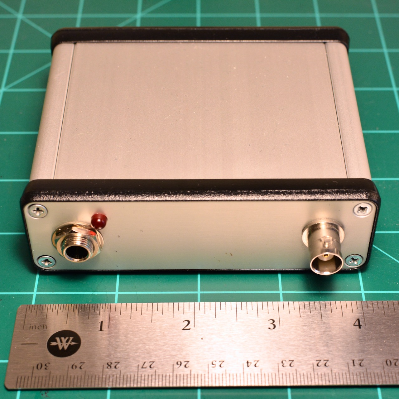
I assembled the components on a Perma-Proto breadboard and crammed it, with a 9V battery, into a small extruded aluminum enclosure from Hammond. The prototype looks great:3
The Accelerominator 3000 in its enclosure.
I use a short TS cable to connect the output to a Tascam DR-40X audio recorder, which is able to treat TS inputs as either mic-level or line-level. (I would have used XLR output instead, but I couldn’t find a cheap panel-mount XLR jack that would fit in my enclosure easily.)
Field recording with an accelerometer
To record interesting sounds, I needed reliable ways to mount the accelerometer onto surfaces. Its end has an integral threaded stud, but the threads are #5-40 UNC, and it turns out nobody uses that thread size in products – by convention, it seems everyone just uses the even-numbered sizes like #4-40 and #6-32. For instance, many vendors sell threaded magnets that could be useful to mount the accelerometer onto metal surface, but none sold them with #5-40 threads. Instead I built my own using a #5-40 washer, a magnet, and Gorilla Glue.
The accelerometer also came with a small box of what PCB calls “petro wax”, which I assume is simply paraffin. This is meant to be used to stick the accelerometer onto a surface temporarily. Because the wax is soft, it attenuates some of the higher vibration frequencies, but it can work for non-metallic surfaces.
(In industrial settings, one usually attaches accelerometers more robustly: either drill and tap a hole into the item being tested, so the accelerometer can be screwed right in, or glue the accelerometer to the surface with cyanoacrylate glue or epoxy. Once the test is done, the glue can be removed with a suitable solvent and the accelerometer carefully pried off the surface. Because the glue is extremely hard, it dampens vibrations very little.)
In any case, how does it sound?
First, here’s the winding and shutter mechanism of my Canonet G-III QL17 film camera (dating from the early 1970s):
Canonet QL17 shutter, via accelerometer:
The Canonet is all-mechanical – no batteries necessary for basic operation. You can hear the winding ratchet mechanism, the shutter firing, and the clockwork mechanism that times the shutter. (In between the two shots, I adjusted the shutter speed to 1/4 second.) It’s like being inside the camera.
For this second test, I wax-mounted the accelerometer on my Unicomp mechanical keyboard, successor to the famous (and famously loud) IBM Model M. Here’s the result of a quick typing test:
Model M typing, via accelerometer:
Bonus round: Measurement microphones
Accelerometers are not the only sensors that use the ICP system. Measurement microphones, such as those made by PCB or by Brüel & Kjær, often use ICP because their users already have ICP data acquisition equipment.
Measurement microphones are an interesting category. They’re designed for engineering and scientific applications: they are robustly built, have extremely flat frequency responses over their useful range, and are designed to be extremely stable, meaning they output a very consistent voltage for a certain sound pressure level. This allows them to be used for precise measurements, and because they can be calibrated to measure sound pressure level accurately, they can be used in noise measurements in applications where there’s a legal noise limit on a product or workplace.
Measurement microphones are almost invariably small-diaphragm condenser microphones, just like the pencil microphones you might use in music recording. (But unlike the large-diaphragm condensers you often see used for vocals, which usually do not have flat frequency responses – a recording engineer chooses the microphone whose tone best suits the singer’s voice.) Just like good-quality studio microphones, they are expensive to buy new. And by “expensive”, I mean they don’t even have a price listed, only a form to request a quote.
But through the magic of eBay, I found a Brüel & Kjær Type 4188 microphone capsule mated to a Type 2695 preamplifier for just $240, including shipping. That’s much lower than you’d typically find either listed for individually. (The same seller lists another Type 2695 for $800!) This deal was slightly undermined by needing to spend $50 on a 12-foot cable with the right connectors (BNC and 10-32 microdot) to connect to my ICP power supply, but I still think I came out ahead. The microphone is astonishingly tiny, just 1/2" (12mm) in diameter and 1.5" (40mm) long, but more sensitive and accurate than all but the most expensive studio microphones.4
Here’s what the same Model M keyboard sounds like, with the microphone perched a few inches above the keyboard on my water bottle, because I don’t own a microphone stand:
Model M typing, via microphone:
Concluding thoughts
Now that I have the equipment to use them, I’m not sure what to use the microphone or accelerometer for. Maybe there’s a niche for ASMR for mechanical keyboard enthusiasts.
I do think it’s interesting that the field recording community has found uses for piezoelectric contact microphones, and even more esoteric instruments like geophones, but I’m not aware of anyone using an industrial accelerometer for any similar recording. Possibly this is because nobody knows they exist; also their cost is likely prohibitive for anyone who just wants to tinker with sound. But used ICP accelerometers are available on eBay regularly for not-outrageous prices, and the ICP power supply above requires about the same skill to build as a good contact microphone preamplifier. If you’re feeling adventurous and don’t mind building your own electronics, maybe it’s worth a try.5
I hope to explore more interesting noises this year when the weather warms up. I’m sure Pittsburgh’s many metal structures and bridges make interesting vibrations, though I’d prefer they not get too interesting while I’m standing on the bridge.
There has been real scientific research about acoustic watermelon ripeness detection, though some of it seems… dubious. See this summary for references. I told this story, including the dubious research results, in the second statistics class I ever taught – an intro course during the summer 2014 session. At the end of the semester, the students brought me a gift: several miniature watermelons. It was touching, except I couldn’t figure out how to carry them all back to my office before the next instructor arrived in the classroom.↩
ACO Pacific does make the IEPE 1248 phantom power adapter system, but I’m afraid to ask how expensive it is.↩
Special thanks to my friend Alex, who owns one of every power tool and let me use his drill press and step bits to make holes for the audio jacks.↩
That’s not to say it’s better than most studio microphones. Studio microphones are usually directional, so they can record a singer or instrument without picking up other noises from the room, echos from the studio walls, or crowd noise on-stage. Measurement microphones are omnidirectional, so isolating your subject is challenging unless you have a soundproof anechoic chamber. Sadly I could not find one of those on eBay for $240.↩
Be sure to get an ICP accelerometer, not a charge-mode or charge-output accelerometer, which requires a different preamplifier. You’ll see many triaxial models that measure outputs in three directions, and hence have three outputs and need three signal conditioners; but a single-axis model should be plenty. Mine has a sensitivity of 100 mV/g, and some are available with even higher sensitivities. Be aware that some have very low sensitivity, such as 2.5 mV/g; these won’t be useful for recording small and quiet vibrations, but since they can withstand extremely high accelerations, they might be useful if you want to record something extremely violent.↩