In a previous edition, we discussed industrial accelerometers: sensitive instruments for measuring vibration inside structures, but also fun ways to listen inside watches, cameras, and watermelons. Unfortunately accelerometers are designed to connect to laboratory data acquisition systems that cost more than a hobbyist is likely to pay, so to use them, we need some kind of adapter to connect to ordinary audio recorders.
My previous project was a simple battery-powered adapter. It provides the 4 mA current source needed by ICP or IEPE accelerometers, at up to 24 V, from a single 9 V battery. A BNC connection supplies the accelerometer with power and receives its signal, and a 1/4" TS jack can be connected to an ordinary field recorder.
But as I tried using my accelerometers in the field, I found the setup too clumsy. A quick recording requires connecting the accelerometer to the adapter, connecting a short audio cable to the jack, connecting the other end to the recorder, and turning on the recorder. And besides the recorder’s battery, I have to worry about the 9 V battery, which is only accessible by unscrewing the adapter’s front panel entirely.
Most recorders can already provide power to microphones over XLR cables. Can we steal that power to supply a microphone, cutting out one battery and making a simpler, easier adapter?
XLR, phantom power, and ICP
Microphones for recording voice and music almost universally use 3-pin XLR connectors. One pin grounds the microphone; the other two are for a balanced signal. Their impedances to ground are balanced, so any electrical noise (from nearby electronics, cell phones, etc.) generates a nearly identical voltage on both signal lines. But the microphone outputs its signal as the difference between the two pins’ voltages, so noise subtracts right out.1
It is a clever design, and it allows power to be supplied to microphones with active circuitry. In the P48 phantom power system, the recorder or mixer applies 48 V to both signal pins through 6.81 kΩ resistors. Again, the microphone signal is the difference between the pins, so applying this voltage is fine; the microphone can tap current off with similar matched resistors and power whatever preamplifier it needs. Under the specification, P48 devices should be able to supply up to 10 mA of current this way.
We need a way to use this current for ICP devices. ICP (Integrated Circuit Piezoelectric), IEPE (Integrated Electronics Piezoelectric), CCLD (Constant Current Line Drive), DeltaTron, and IsoTron are all brand names for a very simple power system that only requires two connectors, not three. The recorder is connected to the sensor with a simple coaxial cable: just one conductor and the shield. The recorder is a current source, not a voltage source, set to roughly 4 mA and capable of supplying at least 18 V (up to 30 V at most). The sensor consumes this current. With no signal, the cable typically carries 4 mA at about 12 V; when the sensor outputs a signal, the voltage fluctuates proportionally, with the current remaining constant.
For those of you who have DIYed microphones and are wondering how they can be powered off a current source, check out ESP’s Project 134 figure 4 for an example—it is surprisingly simple. But for the rest of us, we just need to know: How do we turn P48 phantom power into ICP and return the signal back to the XLR connection?
The adapter schematic
Our adapter will rely on a current-regulating diode, a cheap device that supplies a constant current almost regardless of the input voltage. I’m using the Semitec E-352, which supplies 3.5 mA. I’ll use one pin of the P48 power to supply the current, while the other returns the signal. Here’s the plan:
On left, the XLR connection to the recorder; on right, the BNC connector leading to the accelerometer.
We draw 48V from pin 3. D1 is the E-352, supplying a constant 3.5 mA to the BNC connector. The varying voltage on the BNC center pin is AC coupled to pin 2 of the XLR connector through C1. Pin 3 is kept stable by C2 acting as a low-pass filter. (Thanks to kennjava and Richard Lee on MicBuilders for pointing out the need for C2.) The capacitors must be rated to at least 50 V.
R1 and D2 are for safety. If the phantom power were turned on with no device connected via BNC, C1 could charge to 48 V; D2, a 30V Zener, ensures it can only charge to about 30 V, the maximum rating of most ICP devices. R1 discharges C1 and C2 after power is disconnected.
Those of you who have worked with XLR cables or DIY microphones will notice that this circuit is not balanced: pins 2 and 3 do not have identical impedance to ground. In principle, this makes the XLR output more susceptible to noise. But as we’ll see below, it will be plugged directly into the recorder with no cable. The XLR contacts will be shielded by the metal enclosure, and there’s very little opportunity for interference.
Building a real device
Next, I needed a convenient enclosure to fit the electronics. I discovered Neutrik’s NA-Housing, a simple extruded aluminum enclosure that accepts their D Shape connectors, including the NM3MD-B male XLR connector and the NBB75DSGB BNC connector.2 The XLR connector can be plugged right into a recorder without a cable, making this a convenient recorder-mounted adapter.
For the wiring, I decided to go ahead and make a PCB. I’ve never made one before, and this is a simple enough starting point. The NA-Housing accepts 28mm wide PCBs in its slots, so I made a 28 by 35mm PCB in KiCad. No, my layout is certainly not optimal, but it almost certainly does not matter here.
The refsmmat XLR to ICP adapter PCB layout. The orange region is a ground plane on the back side of the PCB.
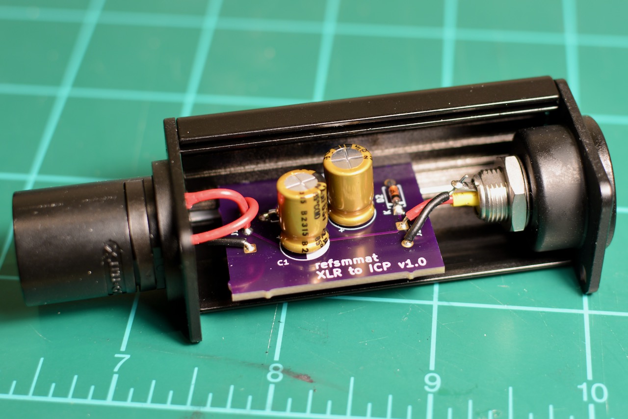
$7.60 to OSH Park later and I had three beautiful PCBs. Then it was simply assembly. Height of the parts is critical to fit inside the NA-Housing; fortunately, Nichicon UFG1J220MPM electrolytic capacitors fit as long as they’re not near the edges of the board.
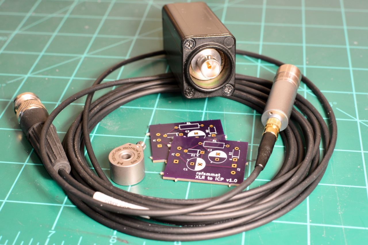
And here are the results:
The guts of the adapter, ready to be sealed up inside its case.The assembled adapter with spare PCBs, an Endevco 7251HT accelerometer, and a coaxial cable connected to a Bruel & Kjaer 4188 microphone on a 2695 CCLD preamplifier.
But how does it sound?
Noisy—if there’s no accelerometer connected. I think this is the noise of the 30 V Zener, though thankfully this disappears immediately when a sensor is connected, since the Zener no longer conducts.
With the accelerometer connected, the noise disappears and we get a clear signal.
Many balanced systems achieve this by sending equal and opposite signals down each pin, so the difference between the two is two times the signal. This is common enough that many people treat it as the definition of a balanced signal; but for rejecting noise, all that matters is that the impedances to ground are equal.↩
In principle this BNC connector is incorrect: accelerometer manufacturers usually use cable with 50Ω characteristic impedance, but this connector is 75Ω impedance. Neutrik makes 75Ω connectors because they are widely used for digital video (SDI) and audio (AES3). But at typical audio frequencies, the impedance mismatch does not matter; the cable is not a transmission line and there will be negligible effect on the signal.↩